OK, this is my first stab at explaining the H31 system. I welcome corrections additions etc.
When
BMW stuck the M70 engine in the E32 body it found that space in the
engine room was tight, very tight. So tight that the old reliable
vacumm booster system could not be used. In addition, the M70 was the
flagship model and something more high tech was called for. BMW took a
look at Citroen's hydraulic systems and decided to create the H31
system. A fully hydraulic system with decent power reserves -- good
braking was possible even if the engine was not turning over.
The H31 system consists of
- a regular hydraulic braking system consisting of
1) master cylinder with reservoir << need specified fluid>>
single ouput line to
2) brake proportioning valve to set front
wheel/back wheel balance <<pressure switches
important??>>
two output lines to
3) ABS system to prevent wheel lockup under braking
<<good E32 - specific description??>>
four output lines to
4) ASC-T system to prevent rear wheel spinning (description here)
two output lines to rear calipers???
5) individual brake calipers
The hydraulic fluid moves in the order shown, from 1-> 2-> 3-> 4-> 5.
The next components are H31 specific.
6) hydraulic pump - uses Pentosin <<details needed>>
7) hydraulic pressure accumulator with pressure adjuster (bombe)
8) booster -- the key to it all.
The booster takes the brake pedal position, converts it into mechanical pressure, and uses it to drive the master cylinder.
The booster has one hydraulic input (from bombe) and one hydraulic relief line (to Pentosin reservoir)
Now how does the booster work and what can go wrong?
This is a cutaway of the booster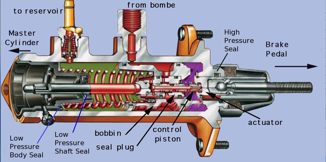
The above diagram shows the assembly in the no-brake state.
There are 3 zones in the assembly.
The
control piston is fixed to the actuator -- depress the brake pedal and
the control piston moves further into the seal plug. This allows
Pentosin from the bombe to enter the PURPLE region behind the bobbin.
The pressure difference between the PURPLE and GREEN regions generates
the force needed to drive the master cylinder -- the bobbin moves to
the left which cuts the flow of Pentosin to the PURPLE region --
this stabilises the brake system. Note that the left hand end of the
control piston is open to the green region to release the pressure.
Release the brake pedal, the control piston moves to the right and the
flow of Pentosin is cut basically to zero. That heavy duty spring in
the green region pushes the bobbin back to the right.
Problems:
a) the HIGH PRESSURE SEAL around the actuator leaks --> Pentosin leaks into the cabin under the pedals
b) the low pressure spring-loaded seal for the output shaft leaks --> Pentosin leaks out of the joint between the booster and the master cylinder.
c) the low pressure body seal leaks --> Pentosin leaks out of the grub screw securing the plastic end cap/spring.
d) the seals on the bobbin leak --> brake power may weaken
d) the pressure release ports (lefthand end of the seal plug become blocked) --> brakes may become partially or fully locked