E34 535 uses electronically controlled ZF transmission - 4HP22EH. The transmission is controlled by the driver through two switches - "S/E/M" Program Switch and "Shifter Selector" Switch. Both switches are subject to wear and may be desired to be reconditioned thereby avoiding expenses.
Here I show how to take them apart for examination and reconditioning...
Transmission Shifter Switch

Transmission shifter switch is opened by prying off clips found around the body
The switch consists of 4 elements:
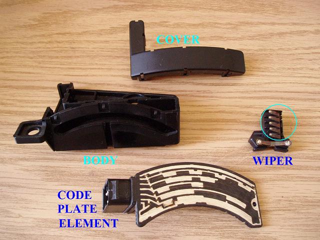
The code plate element provides 7 tracks that are responsible for translation of code to transmission electronics and the speedometer. The wiper provides a bridge for current to traverse from top track to others depending on position of the shifter, so that the code can be established.
Circled are the contacts of the wiper that are connected together. Two bottom contacts are connected separately.
The connection between code plate and the wiper is cricual in order for transmission to shift correctly. If bad connection exists, the electronics acquire incorrect code for the position of the shifter and erratic behavior of the transmission results.
Use mild sanding paper to clean the tracks of the code plate. The wiper should be readjusted by way of gentle pushing away from its frame the connectors to insure good engagement with code plate tracks.

Gently push the screw driver perpendicularly to the connectors towards the base of their mounting. The deformation should be substantial enough for the connectors to be able to reach the tracks of the code plate within closed shifter switch body.
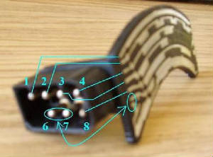
The pins of the code plate connector are marked in the literature numerically from 1 to 8 with missing "5" for this particular application. Use multimeter to establish connections between pins and tracks. For given position of the shifter the wiper connects tracks with top one directing electricity to connector pins thereby creating a code for transmission electronics.
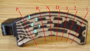
The tracks have variable width to insure connection in particular positions. It is important to make sure that besides being able to reach code plate, the wiper has ability to engage precisely the tracks that must be engaged without shorting ones that must not come in contact, particularly the narrow parts of tracks which are only there to carry connections to wide segments.
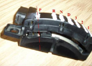
After sanding code plate, displacing the connectors of the wiper away from its frame, and checking that the wiper does not provide undesired connections, the switch is reassembled and is ready for chekup. Using multimeter to ensure that the connection between pin "1" and other pins necessary for given position exists and those not necessary for given position do not exist (!) one can tell whether the operation is proper. In case some tracks short with wiper connectors, the connector tip balls may have to be filed at the sides to establish clearance. In position "Reverse", for example, as seen on picture just above, the pins that have to show the connection with "1" are "4" and "8". Pins "2" and "3" must not provide connections.