The engine of e34 535 uses AFM unit to provide information to the computer about the amount of air that enters. The unit uses a flap reinforced by a spring that continually presses the flap against the air flow. The spring is subject to relatively high temperatures which make possible for it to lose its resilience and gain more lax with time. The result is misadjusted AFM sensor that provides output inconsistent with amount of air that flows into the engine. Oxygen sensor as well is a subject to a change as it ages. Here I provide information on coadjustment of the AFM and oxygen sensor to insure correct operation of the system.
Introduction...
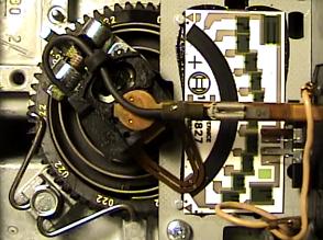
The flap of the AFM is attached to a horn that swings an electrical connector along resistive track providing variable resistance depending on position of the flap and therefore on the amount of air passing through. The variable resistance provides variable current at given voltage, informing the computer of the amount of air entering the engine so that it can adjust the air/fuel mixture...
Some theory...
The spring of the AFM unit is in place to insure that the flap does not wander but is continually pressed against the air flow to provide instantaneous response to the change in the amount of air passing through. In fluid mechanics the scenario is expressed by a relation involving momentum of traveling fluid and the impulse it imparts onto the obstruction:
mV=Ft
m - mass, V - velocity, F - force, t- time.
The velocity of traveling stream is differenet before the obstruction from after the obstruction since the stream experiences compression due to the change in the amount of space provided for passage. This results in formula:
m(V1-V2)=Ft
where V1 and V2 are stream velocities before and after the obstruction. This formula translates algebraically into the relation:
F=(m/t)(V1-V2)
Where m/t is mass of material passing through in unit of time expressed for example in units of "kilogram per second". The flap of AFM unit experiences the force F as the stream passes through which counteracts the effort of the spring to place the flap into position for the amount of air passing through. The formula tells that this force is affected by the mass of air passing in unit time as well as the speed of passage. Essentially "mass per unit time" means density, so density and speed of passing air affects the inclination of the flap.
The density of the fluid can be decreased by providing an opening next to the flap for some air to escape. In this case, the flap experiences less stream density and does not move as far. This type of adjustment is provided by a bypass screw within the AFM unit that channels some of the air before the flap outside, around and past the the flap, back into the intake.
Increasing the tension of the spring attached to the flap makes necessary greater density (and speed) of air to pass through in order to provide given inclination of the flap, therefore, the tension of the spring is also directly responsible for the balance of air/fuel mixture achieved inside the engine. If the spring is tightened - greater amount of air must pass through for given inclination of the flap resulting in leaner mixture. If the spring is loosened - smaller amount of air must pass through for given inclination of the flap resulting in richer mixture.
Since the spring is subjected to high temperature environment it is susceptible to gradual change in its tension, losing its ability to provide as much springiness as it did some time ago. This makes necessary an adjustment.
In order to adjust the spring tension some means of observation are necessary to tell how tight the spring should be. A voltmeter connected to oxygen sensor provides good means of observation as to the strength of the spring. The oxygen sensor is capable of provision of voltage in range 0-1 Volt that reflects the amount of oxygen that passes through its sensing tip. The computer reserves voltage band above .8V for "rich" condition and the band below .2V for "lean" condition. Within these bands the system is not capable of providing adjustment to the mixture which is done by variation of fuel injector pulse time and stores a fault code in the memory respective of the mixture condition. The functional band .2V-.8V privides a "space" of .6V for the system to operate, which is divided in two equal ones of .3V for adjustment within leaner and richer zone. The middle is obviously .5V, equally spaced from .2V and .8V.
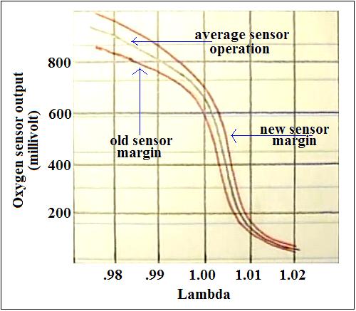
The graph of oxygen sensor response shows average curve and its margins for voltage the sensor provides in relation to the mixture, with ideal mixture of 14.7:1 parts of air to fuel (Lambda = 1.00) providing most efficient combustion. The variation in output voltage within the space .5V +/- .3V results in variation in +/- 1% in mixture from ideal ratio.
This is the region of operation for a balanced system...
The principle...
The principle of adjustment is to set the system into the mode of operation in which the fuel injection data maps essentially control the engine within rough limits of most efficient mixture without interference of the oxygen sensor. The system provides injection maps as means of crude adjustment of the mixture to which oxygen sensor is simply a tool for "fine tuning". The stronger AFM flap shifts the course of operation to leaner mixture domain, the weaker flap obviously shifts the course of operation to richer domain. The objective is to set the course along the acceptable band of operation of the oxygen sensor .2V-.8V within which it can be used as a fine tuning tool without an over run out of margin of injection map.
Tools...
1 - 5 mm allen wrench
2 - Screw driver
3 - Multimeter
4 - Switch
5 - Wiring that satisfies the schematic shown further
Preparation...
The cover of AFM unit must be carefully pried off. The spring is clearly seen right below the horn that slides a contact along resistor track. The wheel holding the spring is secured by a clip which should not be touched. Instead, a crew driver must be placed against a pin protruding next to the wheel. To move, insert the tip of the scredriver between two cogs nearby the pin, and while reclining the screwdriver against the pin, gently rotate the wheel, in increment of one cog. Make sure that the wheel is marked prior to movement.
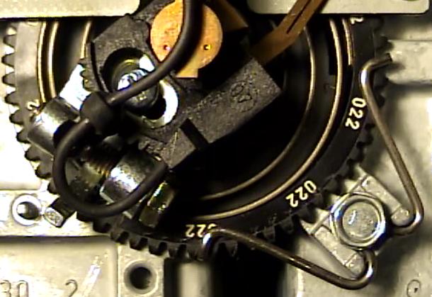
The direction of motion of the flap due to air flow is counter-clockwise from the point of view of the picture frame. the spring is clearly shown to resist that motion, being wound in opposite direction. Turnintg the cog wheel clockwise, tightens the spring, resulting in greater effort to move the flap open by the air flow. This necessitates greater air density, making the air/fuel mixture leaner at given position of the flap.
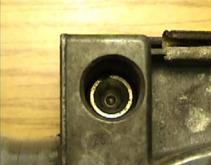
To tune the system, an allen wrench is used on the screw found in a hole on the underside, next to the outlet of the AFM unit. The screw is threaded across an air bypass channel for mixture regulation. As it is turned in, the passage area is made smaller increasing density of air stream before the AFM flap. The flap therefore turns farther in since less air is allowed to escape through bypass channel, making the mixture richer for given air mass flow at filter intake.
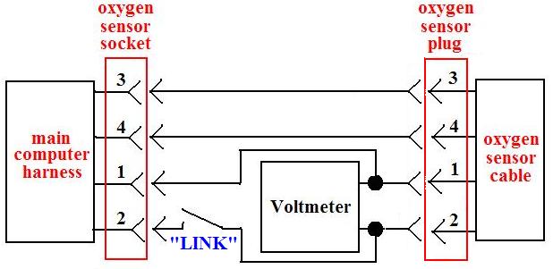
The wiring connects pins 3 and 4 of the oxygen sensor to the main wiring harness in order to provide power to the oxygen sensor. Without the power it cannot stay hot and does not provide voltage.
Procedure...
Disconnect the hose leading to evaporative purge valve from the charcoal canister at the point of connection to charcoal canister to avoid entry of gas fumes into the engine. The hose must be blocked to avoid entry or air as well. Reconnect after the procedure.
Warm up the engine and then stop it. Connect the jumper wires with the voltmeter and the switch as shown. The switch must be in disconnected state.
Turn the screw of the AFM in all the way till it stops. Count 3 turns as you turn now counter-clockwise. This is the base setting of the screw.
Restart the car. Observe the voltmeter display. There are three scenarios one of which can take place:
1 - Various readings that switch fast and haphazardly between about .8V and about .2V
2 - A relatively steady reading above .5V
3 - A relatively steady reading below .5V
Solutions:
1 - Turn the AFM screw one full revolution clockwise richening the mixture. You should see the reading turn steady above .5V. If the reading does not turn steady above .5V the mixture is too lean - turn the cogwheel of the AFM counter-clockwise, by one cog. Reset the screw to base setting - three full turns out from full stop, and repeat the test.
When the reading does set steady above .5V the "rich" margin is good.
Now turn the screw back to base setting, and then turn it once again - one revolution counter-clockwise. You should see the reading turn relatively steady below .5V. If the reading does not turn steady the mixture is too rich - turn the cogwheel of the AFM clockwise by one cog. Reset the screw to base setting - three full turns out from stop, and repeat the test.
When the AFM is adjusted for crude operation within the band of operation of the oxygen sensor, turning the screw clockwise one turn from base setting provides relatively steady reading above .5V, turning the screw counter-clokwise one turn from base setting provides relatively steady reading below .5V. When this condition is satisfied the AFM is adjusted - the screw must be set to base setting before adjustment with gas analyzer.
At base setting the voltage fluctuates haphazardly as a result of engine control by mapped data - the system is not able to keep the mixture at steady state with disconnected oxygen sensor due to the fact that any given stroke is not same as the next one in miscroscopic view. That's the reason why oxygen sensor is used.
2 - A relatively steady reading above .5V signifies rich condition as mentioned just above. Turn the cogwheel of the AFM clockwise by one cog, to allow more air at given position to make the mixture leaner. Reset the screw to base setting - three turns out from full stop and repeat the test.
3 - A relatively steady reading below .5V signifies lean condition as mentioned just above. Turn the cogwheel of the AFM counter-clockwise by one cog, to allow less air at given position to make the mixture richer. Reset the screw to base setting - three turns out from full stop and repeat the test.